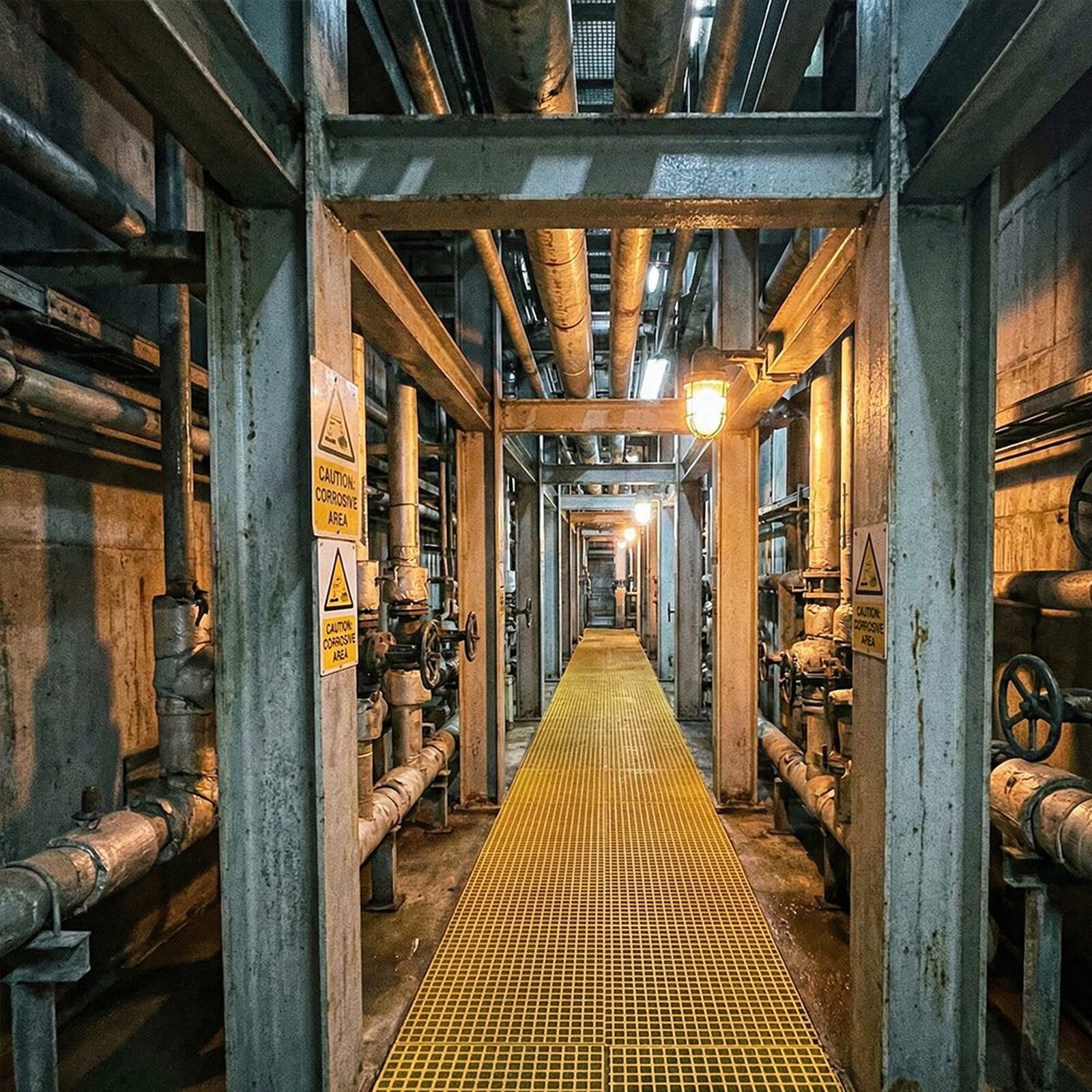
GRP walkway specification starts with the design load the deck must carry, the support spacing between bearers, and the clear width of the walking surface. The structural engineer sets the loading based on what crosses the walkway and how often. That figure, a uniformly distributed load in kN/m² paired with a concentrated point load, sets the rest of the specification: the grating depth, the bearer centres, the deck format and the finished width.
The load a GRP walkway must carry
Design load for a GRP walkway is expressed as a uniformly distributed load (UDL) in kN/m², ranging from around 2.0 kN/m² for standard pedestrian access up to 5.0 kN/m² or more for heavier industrial duty. A concentrated point load, typically around 1.5 to 2.0 kN applied over a 200 mm x 200 mm or 300 mm x 300 mm footprint, is specified alongside the UDL. Both must be satisfied for the deck to comply.
The intended use sets the load class. A walkway carrying only pedestrians, maintenance staff walking to an inspection point, sits at the lighter end of that range. A walkway carrying trolleys, portable tools or maintenance equipment across a plant room pushes the UDL toward 5.0 kN/m² or beyond. Loading categories, whether pedestrian, maintenance with tools or equipment roll-through, determine the deck thickness, the support spacing and the handrail design that follow.
A deck specified too light for the real duty deflects underfoot, feels unsafe to walk on and fails the serviceability check. Specifying too heavy adds cost and dead weight to the supporting steelwork with no structural gain. The use-case assessment is where you and the structural engineer fix the walkway's entire downstream specification.
GRP is the deck material where corrosion is the primary consideration. Three environments justify GRP over steel decking:
- Chemical plants where steel corrodes under process-spill exposure.
- Rooftop plant rooms where corrosion increases total lifecycle cost.
- Coastal installations where salt air accelerates galvanising degradation beyond the expected service life.
In other environments, galvanised steel decking is usually more cost-effective and fit for purpose.
Support spacing and grating span
Support spacing is the clear distance the GRP grating spans between its supporting bearers. It is not the same as the walkway width. Support spacing is a structural dimension governed by the grating's load capacity and depth; width is a traffic dimension governed by who and what needs to pass.
Three variables fix the maximum allowable span:
- The required design load.
- The grating depth.
- The deflection limit.
At a given load, a thicker panel spans further before it exceeds the deflection limit. The common GRP grating depths are 25 mm, 38 mm and 50 mm, and the step between them is real: a 25 mm panel that satisfies the deflection limit at 600 mm bearer centres may fail it at 900 mm under the same load, while a 38 mm panel at that span stays within the limit.
Bearing-bar direction matters, particularly with pultruded GRP grating. The load-bearing bars must run across the supports, spanning the gap between bearers. Pultruded grating installed with the bars running parallel to the supports carries almost nothing.
Moulded and pultruded GRP grating of the same nominal depth can differ in load capacity and stiffness. A span figure from a moulded panel's data does not automatically apply to a pultruded panel of the same thickness.
For a new walkway, the supporting frame is part of the specification. GRP decking bolted to a steel support structure is the common arrangement: the steel bearers carry the span loads down into the primary structure, and the GRP deck sits on top. Because the steel frame and the GRP deck are one structural package, we handle both in-house, designing and fabricating the steel support structure while supplying and fitting the GRP deck, which removes the coordination risk that comes from splitting the walkway across two suppliers.
Deflection limits for GRP grating
The elastic deflection limit for GRP grating is the smaller of 10 mm or span/200 (0.5% of the clear span), whichever governs. For shorter pedestrian spans, the span/200 ratio controls rather than the absolute 10 mm cap, which can bring the practical limit down to around 4 mm on an 800 mm span.
Deflection is a serviceability limit, not a breaking-strength limit. The grating will not snap at 11 mm of deflection. What happens is that the deck feels spongy underfoot, spring-loads when walked on, and can create a trip hazard at the leading edge where the deflected panel meets the bearer. A walkway that feels unsafe gets avoided regardless of its actual factor of safety. On most pedestrian walkways, deflection is the practical ceiling on how far a given panel can span between bearers at a given load.
How to read a GRP load and span table
A GRP load and span table sets out the allowable UDL and point load for each grating depth at each clear span, with the deflection limit already applied. The rows are typically the clear span in millimetres. The columns are the grating depth. The cell values are the allowable loads.
- Find your clear span (the bearer centres minus the bearing width).
- Read across to the column for the grating depth you are considering.
- The cell gives the maximum allowable UDL and point load at that span and depth with the deflection limit satisfied.
- If the allowable load is below your design load, move to the next depth up.
Capacity varies between panels of different construction. A moulded open-mesh panel, a pultruded open-mesh panel and a solid-top panel of the same nominal depth will each have different allowable loads at the same span. Use the load and span table for the actual panel being specified, not a generic industry table. The figures belong to the manufacturer and the structural engineer, and the fabricator works to them. Our GRP grating load tables cover the panels we supply and install.
Open mesh and solid top grating decks
Open-mesh GRP grating drains freely, weighs less per square metre than a solid panel of the same depth, and is the most common walkway deck in industrial environments. Against a steel deck, GRP grating is on average around 80% lighter, per the manufacturers' published figures, which is critical on rooftop plant decks where the dead-load allowance on the supporting structure is tight. Water, light debris and airflow pass through the mesh. The trade-off is that anything small enough to fit through the apertures, including tools, fixings and spilled liquids, falls to the level below.
Solid-top GRP grating presents a continuous walking surface. Nothing falls through. It contains spills and debris on the walkway level, which matters where the walkway crosses an occupied area, a clean process zone, or any space where falling objects are a safety or contamination risk. A solid-top panel is heavier than an open-mesh panel of the same depth, and the supporting steelwork is sized accordingly.
| Open-mesh | Solid-top | |
|---|---|---|
| Drainage | Drains freely; water, light debris and airflow pass through | Continuous surface; contains spills and debris on the walkway level |
| Weight | Lighter per m² than a solid panel of the same depth | Heavier than an open-mesh panel of the same depth |
| What falls through | Anything small enough to fit through the apertures | Nothing falls through |
| Best where | Most industrial walkways; rooftop decks with tight dead-load allowances | Over occupied areas, clean process zones, or where falling objects are a risk |
Mesh size affects what passes through an open-mesh deck. A standard industrial mesh suits most walkway applications, but finer mesh options exist where heeled footwear, small hand tools or wheeled loads such as trolley castors need a flatter bearing surface. Finer mesh also reduces the risk of items dropping through, though it does not eliminate it.
Both formats come with a gritted anti-slip surface finish as standard on walkway decks, giving the rated slip resistance in wet and contaminated conditions. A Pendulum Test Value of 36 or above in the wet condition is the benchmark the HSE accepts for adequate slip resistance. We include the pendulum test data, tested to BS EN 16165, in the project O&M pack, so the slip-resistance specification is auditable from day one.
The deck format interacts with the load and span specification: a solid-top panel's higher self-weight reduces the net live-load capacity at a given span compared to an open-mesh panel of the same depth, and the bearer centres may need to tighten.
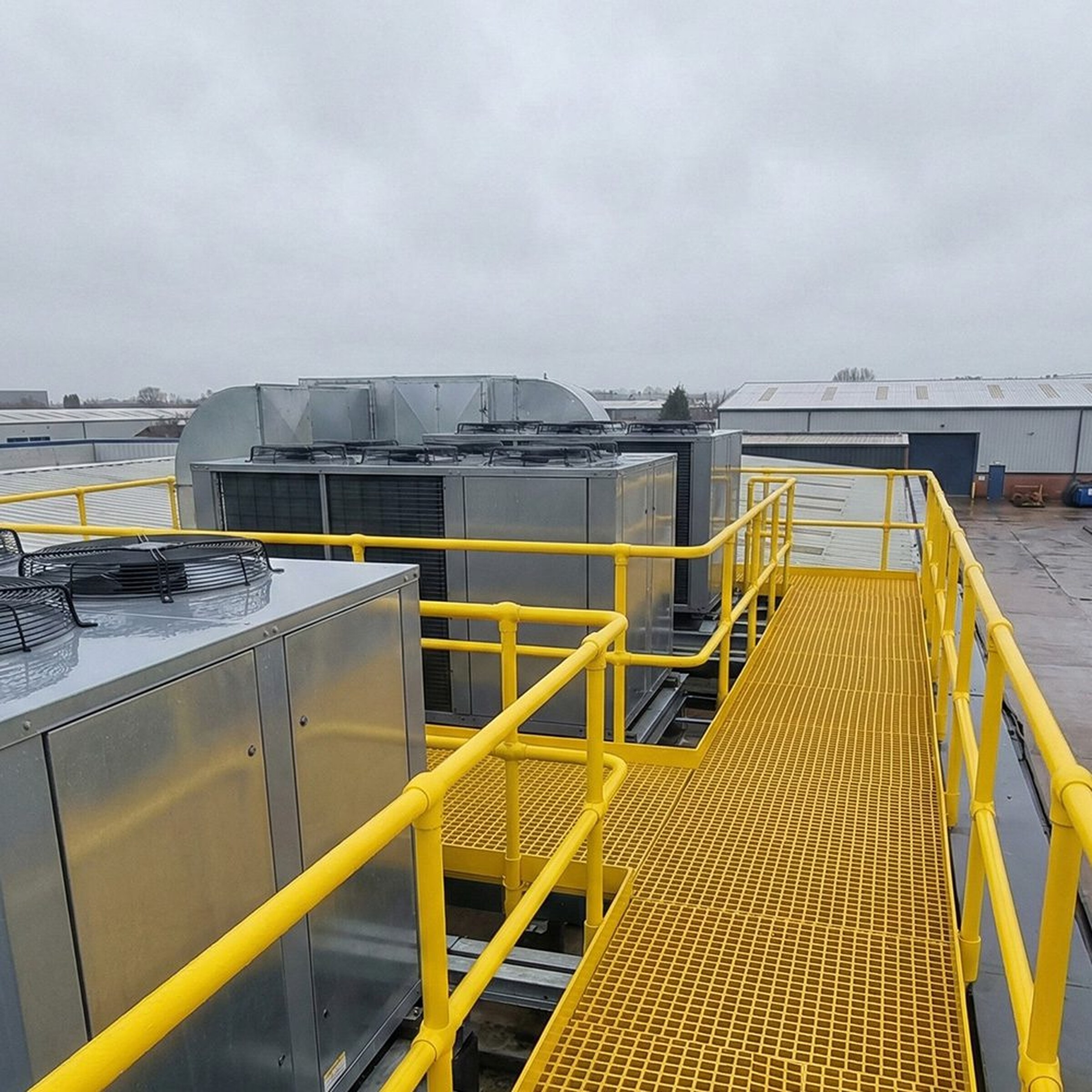
How wide should a GRP walkway be?
Single-file pedestrian access needs a clear width of around 600 mm to 800 mm between the inner faces of the guardrails or edge protection. Two-way traffic, or a single-file route where you are carrying equipment or pushing a trolley, needs around 1,000 mm or more.
Clear width is the usable walking surface, not the overall dimension of the GRP deck panel. Guardrail posts, toe boards and any fixings that project into the walkway reduce the clear width from the panel dimension. Specify the clear width you need and let the panel width and edge details follow from it.
Headroom matters alongside width. A minimum clear headroom of around 2,100 mm above the walking surface prevents head strikes on overhead steelwork, pipework or cable trays. Where headroom is tight, check the walkway routing early in the coordination model rather than discovering a clash at installation.
Where the walkway forms part of a means of escape, escape-route width requirements can override the access minimum. A walkway that satisfies the 600 mm single-file access standard still fails if the fire strategy requires a wider escape route. Check the building's fire-escape provisions before you lock the walkway width.
Standards and regulations for GRP walkways
Three UK standards govern the load, dimensional and grating requirements for GRP walkways:
- BS EN ISO 14122 (particularly Part 2) covers permanent means of access to machinery and industrial plant, including platforms and walkways. It sets minimum widths, clearances and load requirements for the walking surface and any access structure.
- BS 4592 covers industrial-type flooring and stair treads, including GRP open-bar grating. Part 4 (BS 4592-4:2006) covers GRP open bar gratings specifically, and Part 6 (BS 4592-6:2008) covers GRP moulded open mesh gratings. It classifies grating by load and deflection performance and sets the test methods the manufacturer's data is measured against.
- BS EN 1991-1-1 (Eurocode 1, Actions on Structures) defines the imposed-load categories from which the structural engineer draws the design load. The UDL and point-load figures above trace back to the categories in this standard.
All three apply to the same walkway, not as alternatives.
Compliance runs beyond load, width and spacing. Where a walkway is at height or at an open edge, edge protection is required: guardrails and toe boards to the Work at Height Regulations 2005, with guarding provisions under Approved Document K of the Building Regulations. Edge protection is a separate specification from the walkway deck, but it sits inside the same compliance envelope.
Some manufacturer literature and international sources cite US OSHA regulations (1910.x series) for walkway dimensions and loading. These do not apply to a UK specification and should not be substituted for the standards above.
From requirements to a finished walkway
Load, support spacing, deck type and width are one linked specification, not four separate choices:
- The intended use sets the load class.
- The load class and the available span set the grating depth.
- The environment sets the deck format.
- The traffic sets the width.
Change one and the others follow.
Take a maintenance-access walkway at a rooftop plant room, carrying pedestrians and a light service trolley, with around 1,000 mm clear span between bearers. The trolley pushes the load class toward the industrial end, around 5.0 kN/m². At that load and span, a 38 mm open-mesh GRP grating panel satisfies the deflection limit. The corrosive rooftop environment is one of the three cases that justify GRP over galvanised steel. Two-way foot traffic and the trolley width set the clear walkway width at around 1,000 mm. Guardrails and toe boards complete the edge protection. The structural engineer confirms the design load, the manufacturer's load and span table confirms the grating selection, and the specification is ready for fabrication.
Supply, fabrication and installation
Loading calculations are specified by the structural engineer; we fabricate and install to that design. We supply and install GRP walkways as part of our GRP walkway supply and installation service, with the GRP decking bolted to a steel support structure that we design, fabricate and erect from our Rotherham facility. Our welders are individually qualified to BS EN ISO 9606, and the steel frame is fabricated under factory production control to BS EN 1090 Execution Class 2, with the approval records for the welders on your job included in the handover pack. We hold ConstructionLine Gold and CHAS Elite, so if you are running pre-qualification the compliance documentation is already in place.
Our Rotherham base runs two dedicated workshops, one for mild steel and one for stainless and aluminium, separated to prevent carbon cross-contamination. Our own site crew handles the installation, from a single-span maintenance platform to a delivered GRP package like the riser flooring at One Centenary Way for Sir Robert McAlpine. The engineering calculations are retained in the handover documentation, and the compliance boundary between design authority and installation is clear. All steelwork carries a 12-month defect liability period in line with standard JCT terms, which means if something is not right during the first year after practical completion, we come back and put it right.
If you have the design load and the walkway layout, or if you need us to work from a site survey and a performance brief, send us a drawing, a spec, or a one-line brief, and you will get a clear, itemised quote back with a lead time scoped to your programme. On major commercial packages, we return quotations inside one to two weeks. A proper take-off, measuring every member off the general arrangements, deserves more than a guess. If you have a walkway project in the region, we would be glad to talk it through. We cover GRP installation across Yorkshire and can work from your drawings or a site visit.
FAQs
What is the minimum walkway width in a factory?
The minimum walkway width in a factory is around 600 mm for a single-file pedestrian gangway, based on HSE guidance under the Workplace (Health, Safety and Welfare) Regulations 1992. The regulation requires traffic routes in workplaces, including factory gangways and walkways, to be wide enough for the people and vehicles using them but sets no single universal millimetre figure. Where the route carries two-way traffic, wheeled equipment or serves as a means of escape, the required width increases based on the specific layout and use.
What is the typical thickness of a GRP floor panel?
Standard GRP grating panels for walkway and platform decking come in three common thicknesses: 25 mm, 38 mm and 50 mm. A 25 mm panel suits light pedestrian access at short bearer spacings. A 38 mm panel covers most general industrial walkway applications and is the most widely specified depth. A 50 mm panel carries heavier loads or spans longer distances between bearers, typically where the support structure spacing is wider or the duty is more demanding.

Written by
Jacob Hughes
Jacob Hughes is a Director at Universal Industrial Services, one of the UK's leading specialists in structural steelwork, architectural metalwork, and bespoke fabrication. With over a decade of leadership experience in the industry, Jacob oversees all aspects of project delivery - from strategic planning and compliance to client relations and operational excellence. Following the vision set by his father, company founder Neil Hughes, Jacob plays a critical role in maintaining the high standards, safety practices, and innovative approaches that Universal Industrial Services is known for. He is deeply committed to upholding the company's BS EN 1090 certification and CHAS Advanced accreditation, ensuring that every project meets the highest quality and regulatory benchmarks. While Jacob’s day-to-day role focuses on business development and project oversight, he works closely with Universal’s highly skilled engineering and fabrication teams to deliver complex projects across the UK. His leadership supports the company’s mission to invest in people, technology, and sustainable practices, helping clients achieve outstanding results in every project. Outside of work, Jacob is passionate about driving innovation within the steel and metalwork sectors and continues to champion professional development within the Universal Industrial Services workforce.